Aerofoil Selection and Wing Planform
Aerofoil Selection#
The first stage of aerodynamic analysis for the flying wing was a 2D analysis of a series of aerofoil sections suitable for use in flying wings. These aerofoils were suggested for use in flying wings by O'Brien, 1997 , as well as Weyl, 1945 which outlines the requirement for aerofoils that are suitable for flying wing aircraft. The main concern for a flying wing is that the aerofoil must be stable without the need for an offset tailplane - this is achieved by having the CG ahead of the aerodynamic centre of the section Weyl, 1945. This is achieved by implementing a reflex camber, as done by Fauvel and outlined in Weyl, 1945. The aerofoils were analysed between Reynolds numbers of 100000 to 500000, corresponding to a root chord range of 0.2m to 0.5m. The initially predicted cruise velocity, 13.46 ms [Concept 1], was applied along with the kinematic viscosity at the desired cruise altitude - 1.4207 ms.
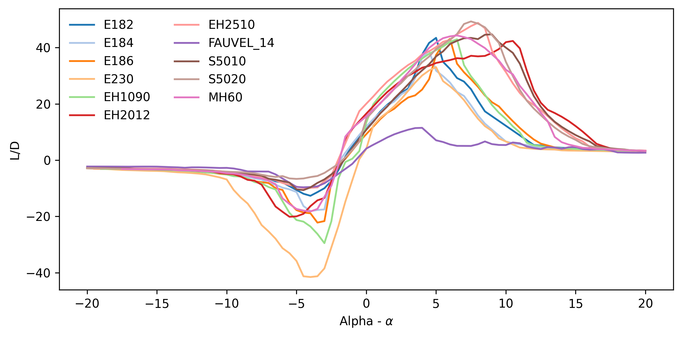
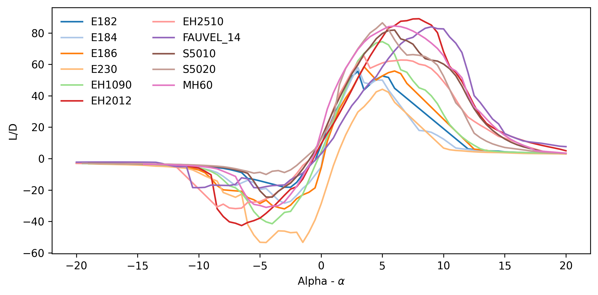
The main consideration for the aerofoil performance was the lift to drag characteristics at a varied angle of attack - the results for which can be seen in figures [1] and [2] at Reynolds numbers of 100000 and 500000 respectively. Analysis of the aerofoil and wing parameter sections were carried out in XFLR 5 using Direct XFOIL Analysis and Wing and Plane analysis. The E230 had a relatively poor performance level at all Reynolds numbers and was therefore the first to be removed from consideration. The E182, E184 and E186 aerofoils possessed high values but at very low angles of attack. It is likely that such an aircraft that would result from this design project would be subjected to frequent deviation in the pitching angle due to the potential effects of wind on such a light structure. This could lead to a resultant low, but non-zero, angle of attack at an unwanted time, potentially causing unwanted rise in altitude and therefore these aerofoils were removed from consideration.
The EH1.0/90 (EH1090) aerofoil was removed for similar reasons - the high lift region occurred at very low angles of attack - and also because the high lift-to-drag region was across a very limited range of angles of attack. The Fauvel 14% aerofoil had a very late region of high lift-to-drag across all Reynolds numbers and was not competitive at lower Reynolds numbers and was therefore removed. The EH2510 has relatively low lift-to-drag characteristics at higher Reynolds numbers and there was a very drastic decrease in lift at the point of stall meaning it is not suitable for this project.
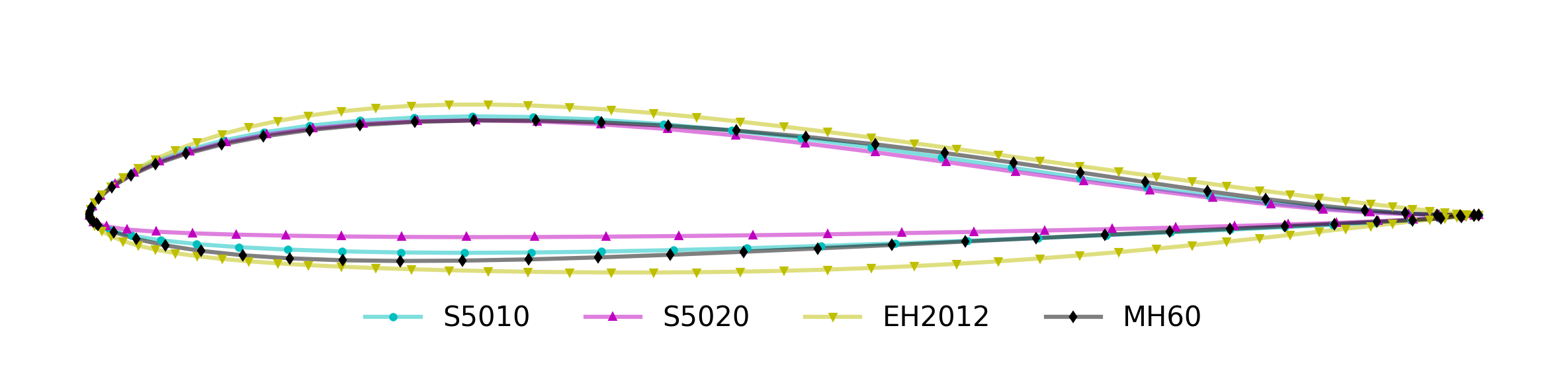
The remaining aerofoil sections are all competitive at the desired Reynolds number conditions. The S5020 aerofoil is very similar to the S5010, differing with a slight decrease in thickness, however, the S5020 does not maintain as high a lift-to-drag ratio for as long a range of values as the S5010, and therefore the S5010 was taken as the preferred aerofoil section. The next stage was to determine the most suitable aerofoil using a common wing design and 3D wing analysis, in particular the lifting line theory solver within XFLR 5. To determine a suitable initial wing area estimate, an empty operating weight of 1.11 kg, estimated from rough component and material masses, was used, giving an estimated MTOW of 5.11 kg. The design point obtained in Concept Design One gives a wing loading value of 12.55 kgm at an aspect ratio of 6.4443, which with the estimated MTOW gives a wing area of 0.407 m. With the given aspect ratio this results in an approximate span of 1.62 m and a chord of 0.251 m to be used in the analysis.
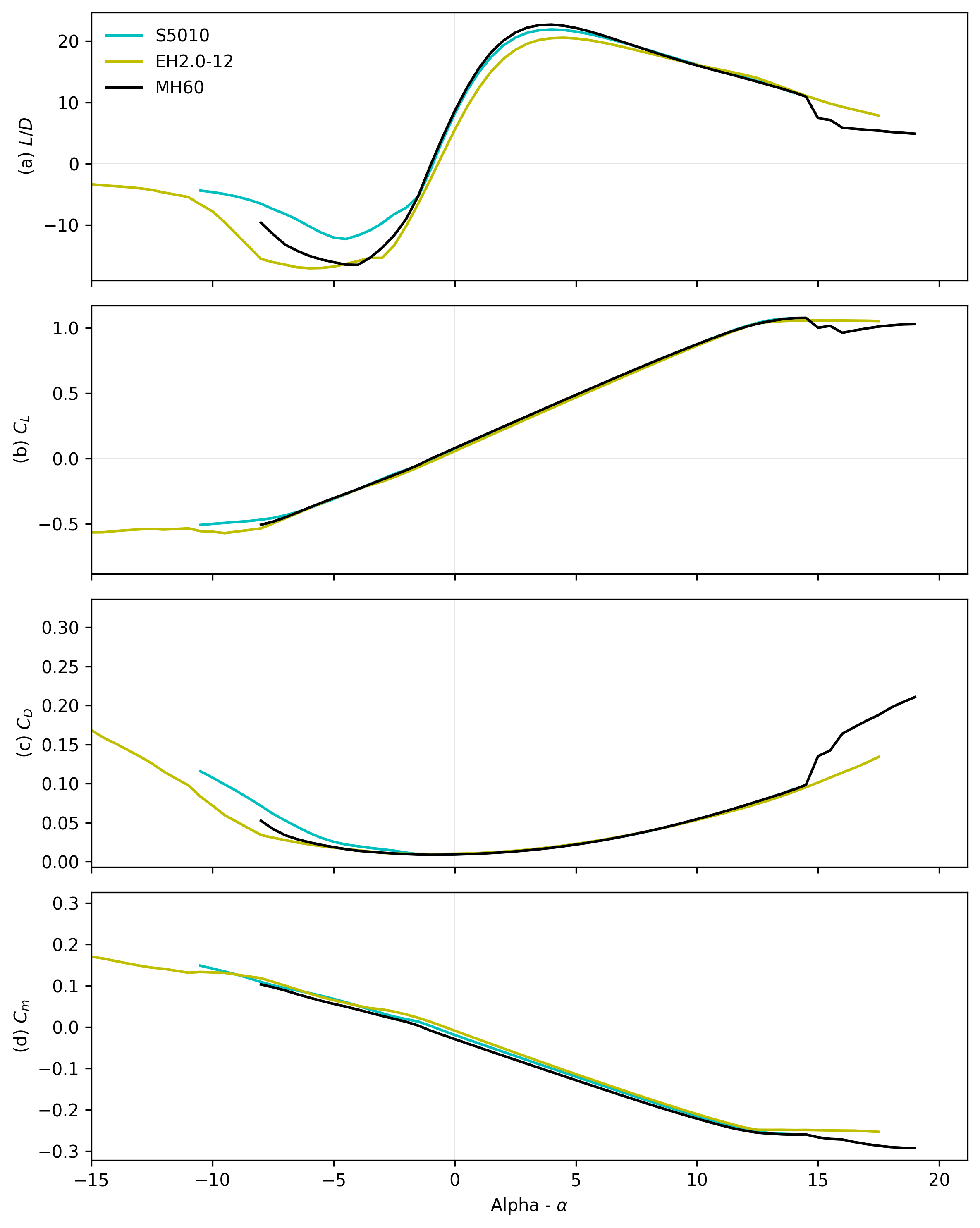
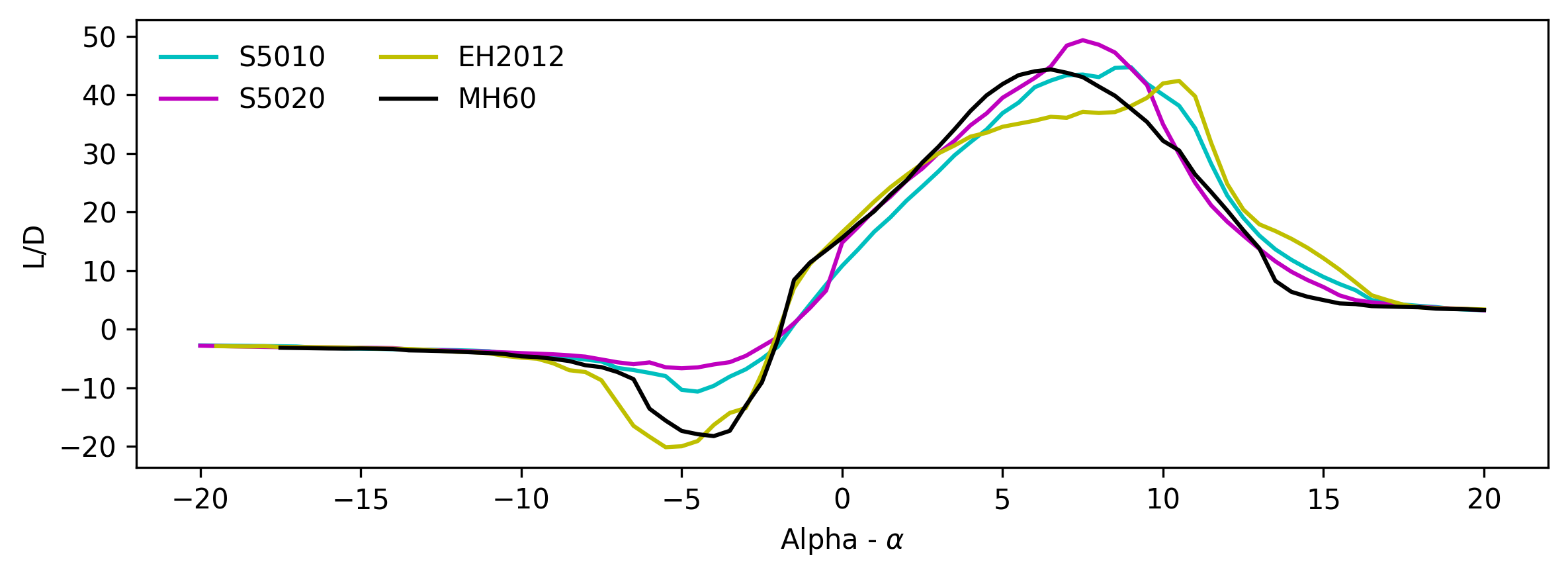
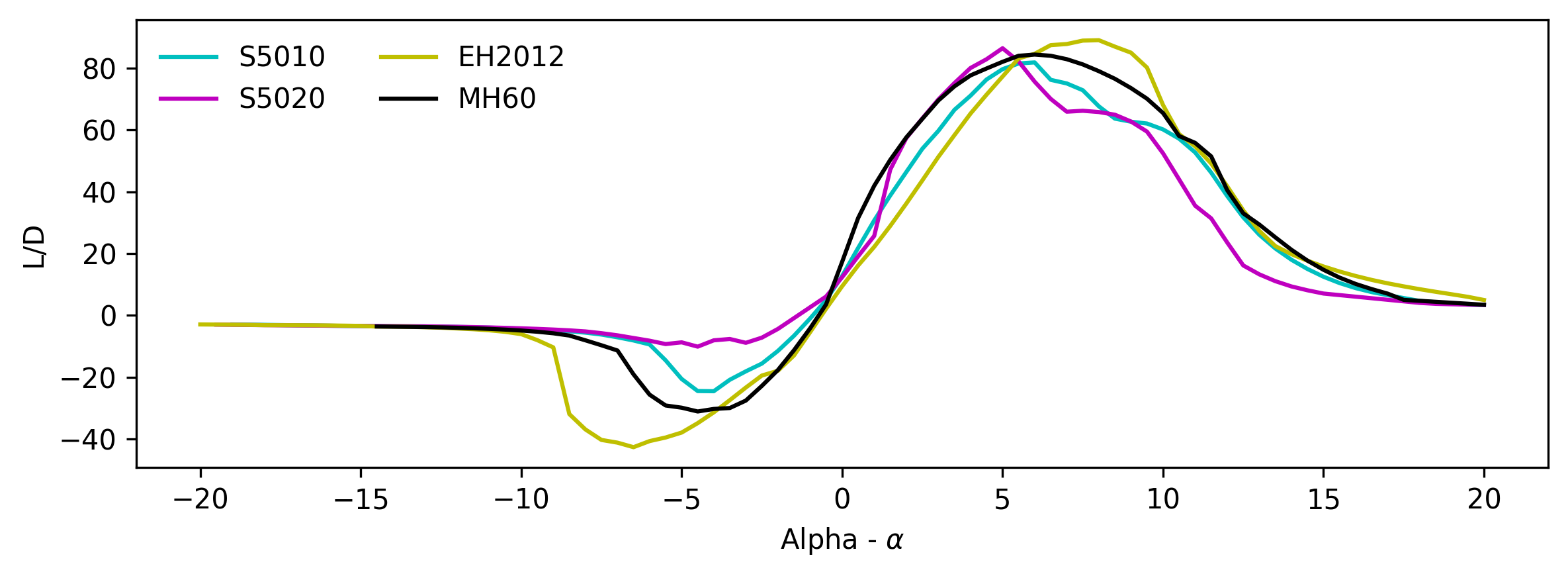
The main aerodynamic parameters from figure [6] are shown in the table below. From these results it is clear to see that the MH60 has the highest peak performance for each aerodynamic parameter compared to the others. The maximum lift coefficient, lift-to-drag ratio and minimum drag coefficient all suggested that the MH60 was the best performing aerofoil. The EH2.0-12 appears to have the lowest relative competitiveness with regards to the parameters outlined and the S5010 is second to the MH60 with little difference in their competitiveness. The magnitude of the pitching moment for the MH60 is the highest of the three as seen in figure [6d], with the EH2.0-12 possessing the lowest value. Figure [6d] shows that the change in pitching moment with angle of attack is very similar for all aerofoils and therefore does not influence the aerofoil selection.
| S5010 | MH60 | EH2.0-12 | |
|---|---|---|---|
| Maximum Lift Coefficient, | 1.075379 | 1.077995 | 1.058003 |
| Maximum Lift-to-Drag Ratio, | 21.89499 | 22.68918 | 20.53778 |
| Minimum Drag Coefficient, | 0.009226 | 0.008997 | 0.010141 |
The table below outlines a basic scoring of the quality and suitability of each wing aerofoil section to the BMFA specified mission. The stall properties category refers to a combination of the maximum lift coefficient at which stall occurs, the angle of attack at which stall occurs and the nature of the stall in the region of angles that have been covered. It was given the highest multiplier due to the necessity for avoiding stall during flight. The overall drag coefficient refers to the drag results seen in figure [6c] and its multiplier is based upon the constant desire for reduced drag. The storage capability category is mainly determined by the thickness of each aerofoil and its integral to consider the internal volume of the wing, i.e. the available storage space. One result of interest is the stall property score for the MH60. This low score is due to the drastic loss of lift after stall where there is a very small margin when nearing the stall angle. Though the S5010 was second to the MH60 in all aspects of performance, the scoring analysis found it to be most suitable.
| Scoring Multiplier | S5010 | MH60 | EH2.0-12 | |
|---|---|---|---|---|
| Stall Properties | 0.4 | 4 | 1 | 2 |
| Overall Drag Coefficient, | 0.3 | 3 | 2 | 4 |
| Storage Capability | 0.3 | 3 | 3 | 4 |
| Overall | 3.4 | 1.9 | 3.2 |
Aspect Ratio#
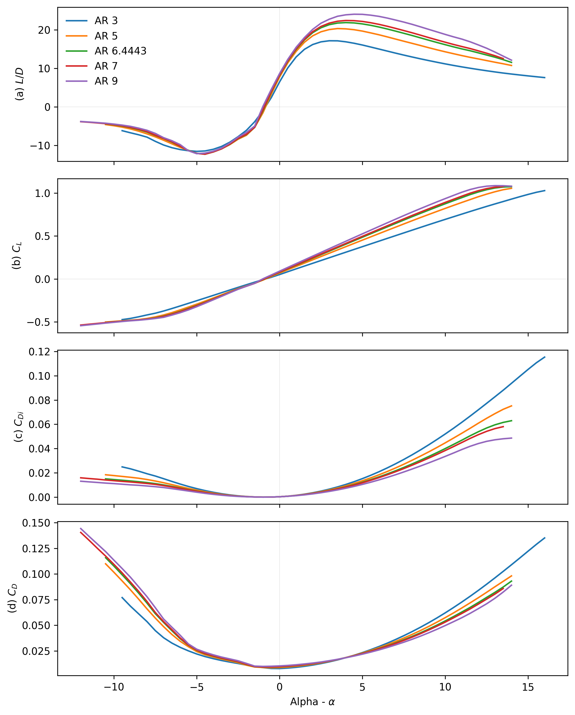
To set an initial aspect ratio, the lift and drag characteristics were found for an S5010 sectioned with aspect ratios ranging from 3 to 9. It was suggested by Chung, 2019 that increasing AR would reduce the induced drag on the wing, but that decreasing AR would reduce the probability of wing tip stalls. Varying the aspect ratio adjusts the predicted surface area as it impacts the initial sizing process [Concept 1]; the chord was also affected and thus adjusted. Figure [7a] shows the lift to drag ratio for varied aspect ratio, the results suggest that the higher aspect ratio resulted in better performance. The lift performance outlined in figure [7b] suggests that the lift curve slope is greater for a higher aspect ratio, however, the stall is lower and thus the highest aspect ratio would not be the optimum choice. The induced drag results (figure [7c]) follow expectations as the higher aspect ratio wings possess lower induced drag. The total drag is also lower at positive angles of attack. An aspect ratio of 7 was chosen for subsequent analysis as the and lift performance of the wing were both competitive. The induced drag was lower than at the initial 6.4443 value and the total drag is not significantly greater than at an aspect ratio of 9. It was also preferable to the AR of 9 as it would reduce the risk of stall at the wing tips.
Taper Ratio#
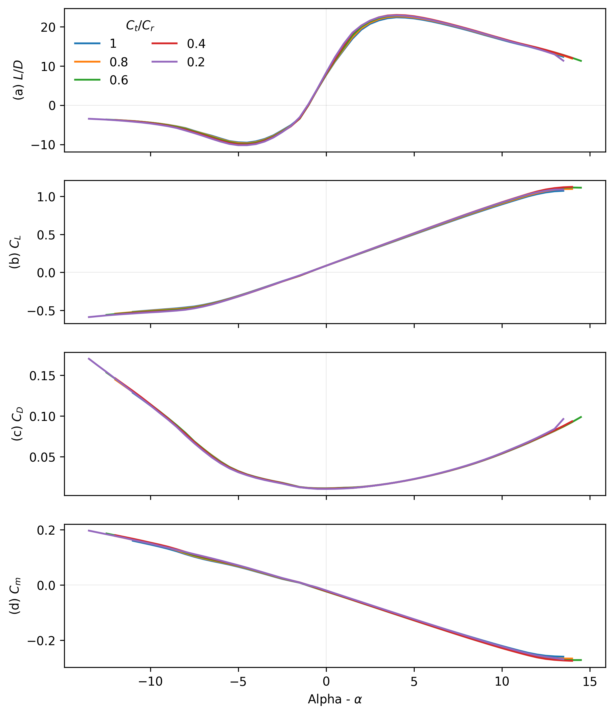
The next design change was to the structure of the wing itself; a change of aerofoil was introduced such that the inner region of the wing would be an S5010 section while the outboard section would be an S5020 section. This was done to reduce the overall thickness at the outboard section as this portion of the aircraft would not need to be as thick for storage purposes; this change in aerofoil shape was initially set to to occur at 20% semi-span. It can be seen from figure [8] that taper ratio has little effect on the aerodynamic performance aside from the maximum lift coefficient being marginally different. The ratios also vary slightly around their respective peaks, where a lower taper ratio results in higher . These differences were not significant enough at to affect selection and instead the desired tip chord length was used to decide a taper ratio. A taper ratio of 0.4 was selected as it provides a sufficient wing tip chord of approximately 0.138 m - this allows for the mounting of sufficiently sized winglets to provide lateral stability. Additionally, the larger the taper ratio, for a given span and constant area, the larger the root chord resulting in more cargo space.
Sweep#
Sweep was also considered briefly; Hepperle, 2018 outlines the importance of sweep as a means of maintaining longitudinal stability. It is necessary for a tailless aircraft that the neutral point be behind the CG, with the neutral point for a taper ratio greater than 0.375 approximated by Hepperle, 2018 as
where, is the position of the neutral point from the nose of the aircraft, the root chord length, the wingspan and the sweep angle at the quarter chord.
| Sweep Angle, [° ] | Neutral Point, [m] |
|---|---|
| 0 | 0.085964299 |
| 10 | 0.149009471 |
| 20 | 0.216100743 |
| 30 | 0.292394121 |
| 40 | 0.385981805 |
| 50 | 0.512072149 |
The neutral points outlined in the table above suggest that, for a CG that lies on the root chord, a sweep angle above 30 is unsuitable. For the planform and weight distribution analysis, an initial sweep angle of 30 ° was set such that the neutral point lay on the root chord. The next stage is to analyse the longitudinal stability of the flying wing with varying the sweep, requiring a rough position of the components within the airframe. This would allow for the change in pitching moment due to a varying angle of attack to be observed and a more suitable and stable sweep angle to be defined.